BraMo 4.0
Bramo 4 is a module to a mobile phone (pager) whith which it is possible to realize the remote supervision. It has four inputs and four outputs. If one of the inputs is activated then the gateway will send through the mobile phone the certain SMS message. It is also possible to connect to the output of gateway for example relay and then operate with this relay with SMS from a different relay. Further description of the function of gateway will be always described with the certain program for processor. It is because just the program of processor decides about the function of the mechanism.
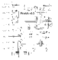
Bramo 3.0 can be used as the output of alarm or it can look after the state of some far-gone mechanism.It also can be used as an electronical lock controlled from MT (keyboard is not needed - hidden lock) etc,etc. There is a scheme of the gateway on the picture (click for larger picture). You can also load the picture in format "*.sch" for Eagle..
Brief description
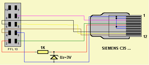
Inputs VST1 to VST4 are activated with connection to OV. Outputs VYST1 to VYST4 are type of open collector, which is profitable for connection of relay. The gateway is connected to mobile phone (MT) through conector with cable SV1 which you can find on this page. Jumper JP2 is made for choice of charging MT. After short-circuit the MT will start to charge. But it is needed that the stabilizator IC2 is completed with a cooler because there will be higher current (power) going thrue it. The LED diode D1 is made for indication of MT connection. Advance warning: When you start, it is first needed to switch on the gateway and then connect to it the switched mobile phone. Otherwise there could happen the "stuck" of SW gateway or MT. That´s why I also recomend to save the power supply of the gateway. MT is saved with it´s own akumulator. If you keep this policy then the running of gateway will be without errors. Jumpers JP1 and JP3 do not have any funcion for the time being . If there will be a change, it will be mentioned in the description of the certain program.
A help with resuscutating of a gateway
From time to time you wrote to me that you have problems with resuscitating of the gateway. That is why I will describe some situations or procedures which are suitable to try if the gateway is not working. You have got the most problems with LED D1, that when MT is connected to the gateway the LED D1 does not light (signalizes the connection and communication with MT) and the gateway is of course not working. The processor is doing as the first thing the test for connection of MT that´s why the problem is probably just in the processor. You first test the power supply of processor (+5V). If it is OK measure the voltage on TX processor (RA1) - it must be in log. level H. If it is not check if the oscillator is oscillating. It is the best to use the oscilloscope or a computer. Measure on the output OSC 2 because there is the output of the inside gate of the oscillator. If there is log.H on TX, measure the voltage on RX processor (R1O). There should be log.L. Then connect the mobile phone to the gateway and there must be shown log.H on RX. If it is not, it is needed to check the connection of gateway with MT. Don´t forget obout the shoaly (dirty) contacts. Because Log.H on RX processor produces TX output MT. If everything is how it should be and LED light does not flash, it is necessary to make a control of the gateway communication with MT. After MT connection the log.H will appear on RX gateway and on this base the processor generates a command "AT" and waits for the answer from MT which must be generated also from the mobile.It is possible to check this process roughly with osciloscope where you can find out if there "doesn´t oscillate" some process on the screen (digital osciloscope has wider posibilities but probably not many people has it). The better control is made by connection of terminal which writes out directly generated process (PC+ program terminal +interface 232/5V). It is possible to avoid testing of communication processor. If you first check with terminal the ability of MT to reply to AT commands and your gateway is connected correct with the cable, it must work. This description is quit brief so if something is not clear for you, let me know. I am not mentioning the description of another errors for now because there were not shown any other serious errors in the past ( I come from your questions). If there will be some other error appearing often I will publish here another description of "treatment".
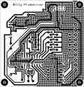
DPS 1 for Bramo 4
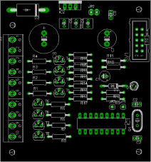
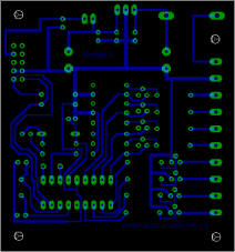
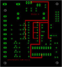
To load a desk of area connections in format *.brd for Eagle.
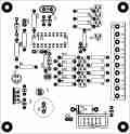
DPS 2 for Bramo 4
Author: Luboš Rückl
E-mail:
lubos.ruckl@quick.cz
This flat connection is cought best with the words of author:
I suggested another flat connection which is smaller then the original and in the main it is one-sided. At the same time I have gently modified the connection. I attach the files for Eagle 4.
Changes compared to original:
a) Terminal plate has a different order of connectors.
Reason: easier flat connection
b) Resistor and Zener diode 3V are not part of the cable but they are on thedesk including the jumper whith which it is possible to include or eliminate the Zener diode.
Reason: easier cable
To load a desk of flat connections and a scheme in format for Eagle (*.brd, *.sch).
You can see in the gallery the picture of Bramo 4 based on this flat connection.
DPS 3 for Bramo 4
Author: Tomáš Chalúpek
E-mail:
tomas.chalupek@oskar.cz
To load a desk of area connections and a schedule in a format for Eagle version 3.54r1 (*.brd, *.sch).
Programms for processor of gateway BraMo 4
Program 4.04
***SIEMENS***
Tested with: S35 v. SW 05, C35i v. 13, will probably work also with other Siemens, see
the table of suitable phones..
To program with: WDT = OFF, OSC = XT
Functions: gateway with this program works with all four inputs and all four outputs. After connection of MT the LED 1 will light up. When one of the inputs is activated (by connection on OV) the the SMS is send, saved on certain place in MT. Before saving SMS messages to MT cancel all previous ones. There can be only the SMS which are needen for the function of gateway. You will send the SMS into MT this way: list in menu -message / to write a message / to make a new text- and you write the certain text. Confirm -OK- and choose -to send text-. You type the phone number which you want as reciever of your SMS and confirm -OK-. Then instead of choise -send- choose -save- and that´s it. Choose the order of saving these SMS so that it matches with certain inputs. When receiving SMS message on MT which is in certain form, it will come to connection of competent output.
VST1 - will send SMS saved in memory on possition no 1
VST2 - will send SMS saved in memory on possition no 2
VST3 - will send SMS saved in memory on possition no 3
VST4 - will send SMS saved in memory on possition no 4
VYST1 - on receiving will unite SMS with text
BM4-Z1
and on receiving will switch off SMS with text
BM4-V1
VYST2 - on receiving will unite SMS with text
BM4-Z2
and on receiving will switch off SMS with text
BM4-V2
VYST3 - on receiving will unite SMS with text
BM4-Z3
and on receiving will switch off SMS with text
BM4-V3
VYST4 - on receiving will unite SMS with text
BM4-Z4
and on receiving will switch off SMS with text
BM4-V4
When using this gateway it is needed to know that when you are uniting more inputs at the same time, the processor is testing them gradually and it will "touch" every other input after settlement of the previous one. The settlement of one activated input lasts about 4 seconds. Despatch of each input can also be delayed by the time needed for settlement of previous SMS. All that means that it is not possible to use inputs for monitoring of short states! Testing of incoming SMS messages lasts about 15 seconds (if the processor is not delayed with sending SMS when despatching inputs).
Program 4.03
***ERICSSON***
Tested with: E768 (version of SW phone 990317 1747)
To program with: WDT = OFF, OSC = XT
Functions: it is the same like with program 4.01. But it can also answer recieved driving SMS. This means that if gateway recieves valid driving SMS, for example
BM4-Z1
(switchning on the output 1), it will automaticly send back the SMS as confirmation of error-free processing of comand. It is necessary for the correct function to save another -fifths-SMS to SIM card of mobile phone with text for example "confirmation of processing of driving SMS". The procedure of saving is the same like with other messages.
Program 4.02
***SIEMENS***
Tested with: C35 v. SW 13, C10, S25, C45 firmware 06
To program with: WDT = OFF, OSC = XT
Functions: gateway with this program is working with all four inputs and one output. After the connection the LED 1 will light up. When one of the inputs is activated ( with connection on OV) then the SMS - which is saved on the certain place in MT - will be send. Cancel all previous SMS messages before saving the new ones to MT. There can be only the SMS in MT which are needed for the function of the gateway. You will save the message to MT this way: you will list in menu - message / write a message / to make a new text - and you write the text. Confirm -OK- and choose -to send the text-. You write the phone number which you want to send the SMS to and confirm -OK-. Then instead of choosing -send- choose -save-. And that´s it. Choose saving of these SMS so that it matches with certain inputs. When recieveing SMS on MT which is in certain form, it will come to connection of output.
VST1 - will send SMS saved in memory on possition no 1
VST2 - will send SMS saved in memory on possition no 2
VST3 - will send SMS saved in memory on possition no 3
VST4 - will send SMS saved in memory on possition no 4
VYST1 - will unite on receiving SMS with text
BM4-Z1
VYST1 - will cut off on receiving SMS with text
BM4-V1
When using this gate you have to know that when uniting more inputs at the same time, the processor is testing them gradually. And it will "touch" every next input after the settlement of previous one. The settlement of one activated input lasts about 4 seconds. Recieved SMS are tested after about 15 seconds (if processor is not delayed with sending SMS).
Program 4.01
***ERICSSON***
Tested with: E768 v. SW 990317 1747
To program with: WDT = OFF, OSC = XT
Functions: gateway with this program is working with all four inputs and one output.After the connection of MT will shine the LED D1. When one of the inputs is activated (with connection to OV) then the SMS is send. This SMS is saved on the certain place on SIM card. You will save the message on SIM card for example: first write it in MT and send on the required number. Then interrupt it during the sending (you will save credit). Then find this SMS in MT and save on SIM card. Choose the order of saving of these SMS so it matches with certain inputs. When you are taking SMS on MT which is in certain format then it will reach to closure (contact) of output.
VST1 - will send SMS saved in memory (SIM) on position no 1
VST2 - will send SMS saved in memory (SIM) on position no 2
VST3 - will send SMS saved in memory (SIM) on position no 3
VST4 - will send SMS saved in memory (SIM) on position no 4
VYST1 - will unite on receiving SMS with text
BM4-Z1
VYST1 - will cut off on receiving SMS with text
BM4-V1
When using this gateway you have to know that when uniting more inputs at the same time-the processor is testing them gradually and it will "touch" every next input after the settlement of previous one. The settlement of one activated input lasts about 4 seconds. The arrived SMS is testing messages after about 15 seconds (if the processor is not delayed by sending SMS).
Connection of cabels between gateway and MT
